2019-07-09
In physics and electrical engineering, the energy of the output signal of a system typically varies with the frequency of the input signal (frequency response). The cutoff frequency (English: Cutoff frequency [1]) is the boundary frequency at which the energy of the output signal of a system begins to drop significantly (in the band stop filter is greatly increased).
Overview
The concept of cutoff frequency is applied to frequency band characteristics such as low pass, high pass, band pass, and band stop in signal transmission channels such as electronic filters. The cutoff frequency is sometimes defined as the intersection of the conduction band and the cutoff band of the electronic filter, such as the frequency at which the circuit nominal output signal is decremented by 3 decibels. In a band-stop filter, the cut-off frequency is defined at the point where the output signal energy rises (or drops sharply) and loses the "block" (or loses "pass") signal effect. In the case of a waveguide or antenna, the cutoff frequency typically includes an upper frequency and a lower frequency.
The concept of cutoff frequency is widely used in electronic engineering, and the concept of cutoff frequency is also used in plasma oscillation.
Electronic science
See also: Bode diagram and decibel
In electronics, the cutoff frequency is the frequency at which the output signal power of a circuit (eg, wire, amplifier, electronic filter) exceeds or falls below the conducted frequency. Typically, the output power is half the conduction frequency at the cutoff frequency and corresponds to the power represented by the position that is reduced by 3 decibels on the Bode plot, since the power ratio is then passed to the output power in the band.
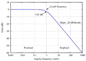
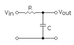
Cutoff frequency of low pass filter
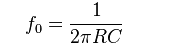
The figure on the right shows a first-order low-pass filter. Its cutoff frequency is determined by:
When the signal frequency is lower than the cutoff frequency, the signal passes; when the signal frequency is higher than the cutoff frequency, the signal output is greatly attenuated. This cutoff frequency is defined as the boundary between the pass band and the stop band.
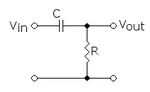
Cutoff frequency of high pass filter
The figure on the right shows a first-order high-pass filter. Its cutoff frequency is determined by:

When the signal frequency is higher than the cutoff frequency, the signal passes; when the signal frequency is lower than the cutoff frequency, the signal output is greatly attenuated. This cutoff frequency is defined as the boundary between the pass band and the stop band.
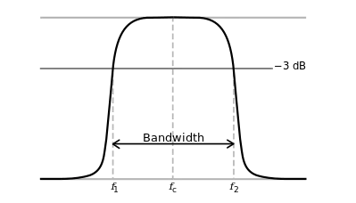
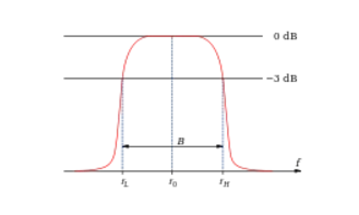
Bandpass filter cutoff frequency and passband width

The signal at the frequency within the passband can pass, and the signal whose frequency is on both sides of the cutoff frequency is greatly attenuated.
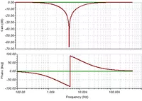
Cut-off frequency and passband width of band stop filter
In contrast to bandpass filters, bandstop filters suppress and attenuate signals in the vicinity of a given frequency; while signals in other frequency ranges pass smoothly. The picture on the right is a Bode diagram with a band-stop filter.
Unlike the bandpass filter, which has two cutoff frequencies, the bandstop filter has only one cutoff frequency (at the intersection of the two grooves in the figure).