
2019-07-08
Introduction to SAW filter technology knowledge
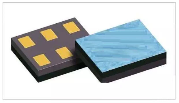
The SAW filter is an abbreviation for surface acoustic wave filter. It is a filter-specific device made of piezoelectric materials such as quartz crystal and piezoelectric ceramic. It is widely used due to its piezoelectric effect and physical properties of surface acoustic wave propagation. In the TV and video recorder intermediate frequency circuit, instead of the LC IF filter, the quality of images and sounds is greatly improved. Surface Acoustic Wave (SAW) is an elastic wave that is generated and propagated on the surface of a piezoelectric substrate material and whose amplitude decreases rapidly as the depth of the substrate material increases.
Principle:
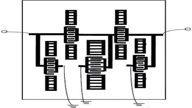
The structure of the SAW filter is shown in the figure. It consists of a substrate made of a piezoelectric material and a comb electrode fired thereon. When the input signal to the large-end surface of the surface acoustic wave filter is input, a mechanical vibration wave having the same frequency as the applied signal is generated on the surface of the piezoelectric material of the electrode. The vibration wave propagates on the surface of the piezoelectric substrate at a sound wave speed. When the wave is transmitted to the output end, the transducer composed of the comb electrode at the output end converts the sound energy into a transaction signal.
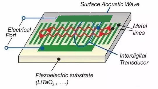
It is not difficult to see from the above that the SAW filter is composed of two transducers. The input transducer converts electrical energy into acoustic energy to emit surface acoustic waves, while the output transducer converts the received acoustic surface. Wave sound energy is converted into electrical energy output. The surface acoustic wave filter utilizes the two transducers on the piezoelectric substrate to generate surface acoustic waves and detect surface acoustic waves to complete the filtering.
Characteristics
The main features of the SAW filter are: high design flexibility, analog/digital compatibility, excellent group delay time deviation and frequency selectivity (optional frequency range 10MHz ~ 3GHz), small input-output impedance error, low transmission loss, anti-electromagnetic interference (EMI) Good performance, high reliability, small size and light weight (the size and weight are about 1/40 and 1/30 of the ceramic dielectric filter), and can achieve a variety of complex functions.
The characteristics and advantages of the SAW filter are adapting to the requirements of modern communication system equipment and portable telephones in terms of thinness, shortness, high frequency, digitization, high performance, and high reliability. The disadvantage is that the required substrate material is expensive, and the substrate orientation, cutting, grinding, polishing and manufacturing processes are required to be high.
Impedance matching:
For high frequency circuits, inductive matching between circuits is important. Inductance matching means that the output impedance of the transmitting end circuit is consistent with the input impedance of the receiving end circuit on the transmission line of the signal. After matching, the power of the transmitting end can be transmitted to the receiving end with a large degree.
The matching circuit uses capacitors and inductor, but the actual capacitors and inductors are different from the ideal components and have losses. Indicates that there is a Q value for this loss. The larger the Q value, the smaller the loss of the capacitor and inductor.
Q value of the inductor and loss of the high frequency circuit:
The magnitude of the Q value of the inductor used in the matching circuit also affects the loss of the high frequency circuit.
In order to confirm this, we used a SAW filter (passband 800MHz band) and RF inductors, and replaced the RF inductors with different Q values in the matching circuit to measure and compare the insertion loss of the SAW filter.
Figure 1 shows a circuit diagram. This circuit, although a matching circuit, has only one RF inductor.
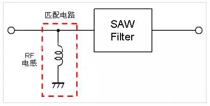
Figure 1: SAW filter and matching circuit
Fig. 2 shows the frequency characteristics of the Q value of the RF inductor that has been replaced this time. Table 1 shows the structure, size, and Q value (Type value at 800 MHz).
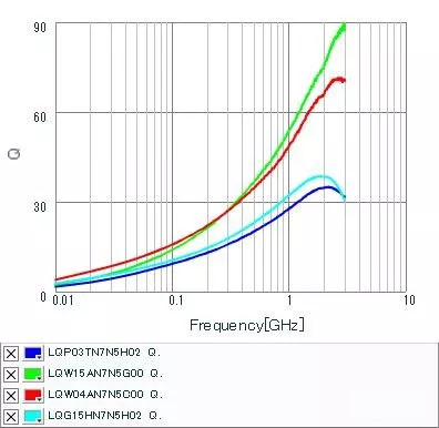
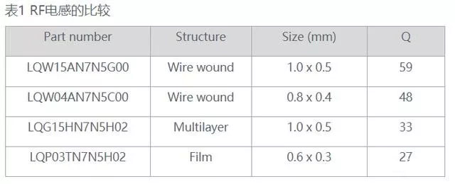
Figure 2: Comparison of Q values of RF inductors (both 7.5nH)
The overall characteristics of the SAW filter when the RF inductor of the matching circuit is replaced are shown in Fig. 3. The passband characteristics are shown in Fig. 4.
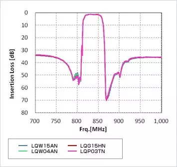
Figure 3: Overall characteristics of the SAW filter
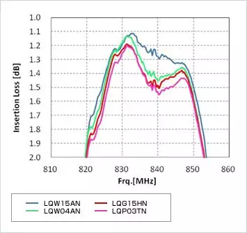
Figure 4: Passband characteristics of the SAW filter
From the characteristics of the pass band of Fig. 4, it can be confirmed that the insertion loss of the SAW filter differs depending on the RF inductance used. This level of loss in high frequency circuits is becoming more and more important.
From the experimental results, the larger the Q value of the RF inductor (the smaller the loss), the smaller the insertion loss of the SAW filter. That is to say, the size of the inductor loss is the size of the SAW filter loss including the matching circuit.
Please note that the high frequency components (this time are SAW filters), matching circuits, frequency bands, etc., will also vary in loss.
Inductance deviation and influence on matching circuit:
In addition, the actual inductor has an impedance value of 1.0 nH, 1.1 nH, and 1.2 nH. When making a match, it is sometimes necessary to fine-tune it with a detailed constant step. At the same time, the deviation of the impedance value (standard deviation) becomes a matching standard deviation, and in order to satisfy the necessary characteristics, an inductor with a small deviation is sometimes required.