
2019-07-09
Since the attenuation effect seriously affects the operation of the communication network, PIM is receiving more and more attention in the field of wireless communication. Inter-modulation occurs whenever a signal above two frequencies encounters a nonlinear electrical junction or similar material. The result is a signal we don't want. The frequency of this signal can be calculated from the original original frequency, which can result in a reduction in system capacity and/or a reduction in call quality.
The reduction in capacity and the reduction in call quality in the cell will result in a reduction in revenue for the wireless communication service provider. When an affected customer loses confidence in the service provider and changes to use a competitor's service, the economic loss of the service provider will be unpredictable.
Through conversations with engineers and technicians around the world, Summitek discussed issues related to inter-modulation with device manufacturers, downstream suppliers, field managers and service providers. Summitek combines the knowledge gained through the manufacture and development of its PIM analyzers, the basic methods of PIM measurement, and the test performance of the Summitek analyzer to form existing perspectives and perspectives. Summitek recommends the following:
· Under the realistic situation of emphasizing cost performance, it is difficult to meet the large demand of the market by adhering to the principle of “low” inter-modulation.
· PIM evaluation equipment should use dynamic measurement methods.
· Because frequency is dependent on the characteristics of many devices and their subsystems, fixed frequency test methods may not be suitable.
Reasons for the formation of PIM
Design, manufacturing, and maintenance are all reasons for inter-modulation.
In terms of inter-modulation, good design is a necessary condition, but not a sufficient condition for success. At the same time, many companies believe that inter-modulation can be easily controlled by some design rules. Avoid using ferrous materials and minimize the number of joints. All joints in the design must be precise and maintain a good connection under sufficient pressure. Solder or cold weld all joints; avoid direct contact between different materials; plate all surfaces to prevent oxidation; ensure uniform plating and sufficient thickness. Although these rules seem simple, achieving them perfectly is the key to success. Minor deviations in the ideal process can lead to intolerable inter-modulation. What may happen in a real environment: simple connection between components; unscrupulous torque of screws and fasteners; poor soldering at joints; insufficient thorough cleaning of parts before plating; contaminated plating bath; structure of electroplated materials; Use the wrong material; poor adhesion to plating.
Once you have the components that are designed and manufactured to perfection, the next challenge is assembly and system installation. All nodes are potential producers of inter-modulation, so each connection point is a potential source of problems. In the presence of mechanical stress (torsion of the cable, torsional load of the joint section, joints above/below torque), the test of the joint in a good external environment is still unreliable.
In summary, the achievement of inter-modulation metrics for all connected components does not guarantee that their subsystems will also achieve inter-modulation metrics.
Again, the natural factors are the natural enemies of the network that are exposed to nature. Winding caused by wind, daily temperature changes, various forms of moisture, heat load caused by sunlight, dust in the air. Each of the above conditions will ruin the quality of the device in the network and eventually lead to the collapse of the channel. Joint attenuation, junction separation, moisture intrusion, material oxidation, and dust contamination all increase inter-modulation and reduce receiver sensitivity. This result is the actual situation of the cellular network under design potential.
Test Method - Quantify Inter-modulation Performance
Good communication quality requires a tolerable carrier-to-interference (C/I) ratio, so our hope that the interference "I" is as small as possible. In the ideal case, the interference "I" is always less than the noise floor of the receiver. One of the reasons for the interference we don't want to see is passive inter-modulation.
A typical indicator requires that when two +43 dBm carrier signals are injected into the device during the test, the passive inter-modulation cannot be greater than –110 dBm, or -153 dBc. In other words, this indicator requires a ratio of 1:2,000,000,000,000,000, or equivalent to measuring the distance between the Earth and the Sun with an accuracy of 0.1 mm.
· Previous
Previously, the usual practice of measuring PIM was to measure the inter-modulation power produced by injecting two fixed-frequency, 20-watt continuous-wave signals per channel at a fixed frequency. This scheme is consistent with the method of measuring PIM (IEC TC46 WG6) defined by the International Standards Committee.
To implement the necessary test equipment, the classic approach is to use a stacked approach to feed two signal synthesizers to two high power amplifiers. These two high-power amplifiers are connected to a number of devices that are used to synthesize, filter, and duplex signals. The processed signal is then sent to a spectrum analyzer for monitoring and display through a low noise amplifier. A power meter is used to periodically adjust the transmit power to compensate for the offset.
It is obviously a difficult process to build a passive inter-modulation platform by means of a stacking method. Moreover, due to many of the discrete devices, components, and interconnected cables, measurement results are sometimes difficult to reproduce, and equipment is often unstable and susceptible to damage. If this is not enough to convince you, this test method is time consuming. Moreover, we have begun to realize that such test results are uncertain and easily misunderstood.
· just now
Based on an understanding of the implementation of PIM measurements (and related deficiencies), Summitek set the following design goals: to build a test set with high quality, repeatable test methods. Make the device easy to set up and use. Guarantee the world's advanced level by providing new and useful tools. In order to establish a clear basis for comparison, standardization is introduced into this complex test method. Keep up with current technology trends and test standards. Listen to the consumer's recommendations and categorize them to provide the most comprehensive, easy-to-learn test equipment possible.
This has led to three important design features of passive inter-modulators:
1. Highly integrated design: Minimizes the number of external components by assembling all RF components in a single chassis, which increases reliability, stability and repeat-ability.
2. High-speed digital receiver technology. Summitek's analyzer's speed and frequency sensitivity make it possible to:
· Simultaneous measurement of multiple inter-modulation products.
• Measure and record some transient conditions, such as passive inter-modulation pulses, and inter-modulation changes due to mechanical and environmental influences.
• The inter-modulation sweep measurement feature verifies the implementation of the entire specified frequency range.
3. Creative new test performance: The final equipment is simple, efficient and rigorous. Therefore, this test method is very practical for ensuring product quality and network integrity.
Most measurement methods are based on a pair of independent carrier frequencies. Due to wireless communication standards, this frequency is often placed at the edge of the transmission band.
Take the example of measuring devices operating in the PCS1900 band. Typically, the test setup carrier 1 is 1930 MHz and carrier 2 is 1990 MHz (Note: There are some passive inter-modulation test equipment based on design reasons, one carrier must be set in the receive band and the other carrier set in the transmit band. The correctness of this test method is controversial). The test begins after the transmit frequency and power are determined and the spectrum analyzer is set to the inter-modulation response. During the test, it is important not to bump the device under test and the test instrument to avoid data spikes due to instability when the spectrum analyzer scans just through the inter-modulation band.
Experience has taught us that there are many limitations to this method of measuring passive inter-modulation, and there are many hidden potential problems.
Dynamic measurement
Regardless of environmental factors, although the performance of the product is stable due to optimal design and manufacturing, the passive intermodulation response of the device and subsystem is subject to significant changes due to stress. In dynamic measurements, we apply some appropriate external stimuli to monitor intermodulation performance.
The dynamic measurement of cable assembly has received a great deal of attention. We must note the intermodulation produced by the joint/cable interface, taking into account the intermodulation produced by the cable itself (intermodulation caused by microcracks on the solid conductor cable and discontinuous contact of the braided cable). Testing includes intermodulation when the cable is in a bent state, or when the joint/cable surface is in a torsional state.
In our view, in a wireless communication network, all components of the base station transmitter are subject to intermodulation. Summitek used the two test methods to perform passive intermodulation tests on all devices under test using Summitek's analyzer. The two methods are the "knock" experiment and the "deflection" experiment. The “knock” experiment is simply tapping the device and observing the intermodulation response. For example, an adjustment screw that frequently hits the filter produces a high intermodulation value. When the tap is stopped, the intermodulation value sometimes returns to the original low intermodulation condition, and sometimes it remains in the high intermodulation situation. The “tap” experiment is very useful to prove that the shielding device and cable will one day fail.
In the next example, we will have a test chart as an illustration. During this experiment, we used a Summitek analyzer with ribbon recording paper to record the data of the intermodulation response during the experiment. The device under test is a bandpass filter of the PCS1900, and we are concerned with the intermodulation changes caused by tapping. Another experiment after this is to show that when the temperature changes, the intermodulation index of the device will rapidly deteriorate.
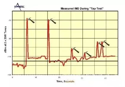
Figure 1: Dynamic Intermodulation Measurement
The "deflection" experiment is to observe changes in intermodulation when a suitable lateral force is applied to the joint of the device under test. The joint is not sufficiently fixed to the body of the device, or the internal emission structure of the device is not strong, which will cause intermodulation.
Sweep measurement
So far, the accepted method of passive intermodulation has been to set the carrier to two fixed frequencies and then measure the resulting intermodulation. These two fixed frequencies are usually set in the transmit band, but this is not necessarily the case. We have found that such test methods are not very suitable for intermodulation measurements of a large part of the device. Because the intermodulation characteristics of these devices vary with a frequency dependent function. The intermodulation test equipment produced by Summitek's Passive Intermodulation Analyzer has a multi-band sweep function that solves this problem and is simpler and more practical.
The following is an obvious example to demonstrate the advantages of the swept intermodulation tester. In the experiment, the duplexer of the PCS1900 band with a problem with the connector was tested. It should be noted that the damage of the device connector is caused by excessive torque, and it cannot be found by visual observation and sweep measurement of return loss. The figure below is a comparison of the return loss of a "good" duplexer and a "bad" duplexer.
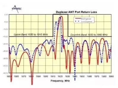
The “good” duplexer achieved a specification of –115 dBm over the entire frequency band, but when the transmit carrier of the “bad” duplexer was moved from the passband edge, its intermodulation index deteriorated rapidly. If the two duplexers are only tested using the carrier of the passband edge, they can pass the quality assessment screening.
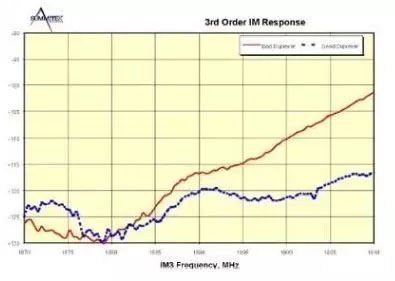
In order to fully display the characteristics of the device under test, Summitek's frequency-modulated passive intermodulation analyzer records the intermodulation values of each of the two channels when scanning across the entire transmit band (ie, the downlink), however, Only one carrier is in the scanning state at a time, while the other is maintained at a fixed frequency at the edge of the passband. In the following example, when carrier 2 is scanned in the 1950 to 1990 MHz band and carrier 1 is fixed at 1930 MHz, the resulting third-order intermodulation signal is between 1870 and 1910 MHz.
The measurement results can be recorded into a document and copied to the computer's clipboard so that it can be pasted into another application, or it can be directly hard copied to the printer for printing.
to sum up
Since wireless communication service providers are committed to maintaining and winning customers, controlling passive inter modulation distortion is directly related to the economic interests of service providers. At present, the passive inter-modulation existing in the cellular network affects the capacity and call quality of the base station. Therefore, in order to achieve better network performance, passive inter-modulation indicators must be valued and measured and controlled throughout the design, manufacturing process, and even after installation at the base station.