
2019-07-09
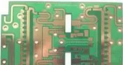
1.the introduction of high frequency circuit
The high-frequency circuit is a radio circuit, but it does not involve microwave circuits. (Microwaves are used to process circuits above one gigahertz, starting with physics electromagnetic fields, very different from our common circuits), for radio wave emission, Receive, modulate, demodulate, amplify, etc.
Digital circuits process digital signals. Digital signals only have high and low signals. For example, digital circuits in CMOS process have a working range of 0-3.3 volts, 0-0.8 volts is considered low, 2.4-3.3 volts is considered high, and other voltages It is considered to be invalid, and all electrical signals are divided into a sequence of high and low levels. It is suitable for high-speed processing, high-precision processing, and computer interface, and is directly processed by a computer.
The analog circuit does not distinguish between levels, and all continuous signals are processed together (the macroscopic physical quantities of nature are continuous) for power, amplification, filtering, and so on.
The analog circuit and the high-frequency circuit are actually very close, except that the circuit operates at a high frequency, and the physical characteristics of many components are changed, and the processing method and the problem to be processed are different.
High frequency circuit performance index
High-frequency small-signal amplification has two forms of resonant amplification and wideband amplification. The performance indicators mainly include the following items.
1.gain
High-frequency circuits, like low-frequency circuits, have indicators of voltage gain and power gain. For the resonant amplifying circuit, it means that at the resonant frequency f0, for the wideband amplifying circuit, it refers to the bubble enveloping at a certain frequency.
2. Passband
Similar to the low-frequency circuit concept, for the resonant amplifier circuit, the passband refers to the difference between the two corresponding frequencies whose normalized amplitude drops to 0.707 with respect to the resonant frequency f0; for the wideband amplifying circuit, the corresponding with respect to a certain frequency definition.
3. Selectivity
The selectivity is mainly for the resonant amplifying circuit, and the characterization circuit selects the ability of the useful signal to suppress the unwanted signal, which is usually measured by the rectangular coefficient and the suppression ratio, and is based on the resonant characteristic curve of the circuit.
4, noise figure
When the amplifier circuit works, irregular movement of carriers occurs due to various reasons, and noise is formed inside the circuit, which affects the signal quality. This effect is usually described by the ratio of signal power Ps to noise power Pn (referred to as signal to noise ratio). The noise figure is defined as the ratio of the input signal to noise ratio to the output signal to noise ratio.
5, stability
The stability of the high-frequency amplifier circuit refers to the stability of its main performance when the working state or condition changes. For example, changes in ambient temperature or fluctuations in the supply voltage can affect the DC operating state of the amplifying circuit; the parameters of the circuit components also change, resulting in a change in the gain of the amplifying circuit, a shift in the center frequency, and a distortion in the resonant curve. Even self-excited and completely unable to work.
High frequency circuit grounding principle
For circuits and digital circuits with higher operating frequencies, the grounding of the grounding wires is increased due to the inductance of the components and the layout of the circuit itself. Therefore, a grounding method widely used in low-frequency circuits is widely used. If used in high-frequency circuits, it is easy to increase the impedance of the grounding wire, and the stray inductance and distributed capacitance of the grounding wire may also cause mutual coupling between the circuits, thereby making the circuit unstable.
In order to reduce the ground line impedance and reduce the stray inductance and distributed capacitance between the ground lines, the mutual coupling between the circuits is caused. The high-frequency circuit adopts the principle of close grounding, that is, multi-point grounding, and the system ground of each circuit is connected to the low-impedance ground. Generally speaking, when the operating frequency of the circuit is higher than 10MHz, multi-point grounding should be adopted. the way. Since the grounding of the high-frequency circuit is to minimize the stray inductance and distributed capacitance of the ground line, the implementation method of the grounding is very different from the low-frequency circuit.
2.the introduction of RF circuits
RF is referred to as RF, and RF is RF current. It is an abbreviation for high-frequency AC-changing electromagnetic waves. An alternating current that changes less than 1000 times per second is called a low-frequency current, and a frequency greater than 1000 times is called a high-frequency current, and a radio frequency is such a high-frequency current. Cable TV system is based on radio frequency transmission
In the theory of electronics, a current flows through a conductor, and a magnetic field is formed around the conductor; an alternating current passes through the conductor, and an alternating electromagnetic field is formed around the conductor, called an electromagnetic wave.
When the electromagnetic wave frequency is lower than 100khz, the electromagnetic wave will be absorbed by the surface and cannot form an effective transmission. However, when the electromagnetic wave frequency is higher than 100khz, the electromagnetic wave can propagate in the air and be reflected by the ionosphere at the outer edge of the atmosphere to form a long-distance transmission capability. We call the high-frequency electromagnetic wave with long-distance transmission capability as radio frequency. English abbreviation: RF
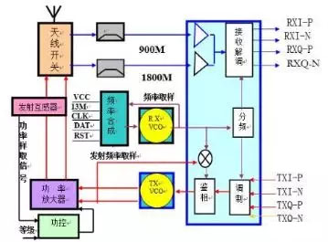
RF circuit composition and characteristics
The ordinary mobile phone RF circuit consists of three major circuits: the receiving path, the transmitting path, and the local oscillator circuit. It is mainly responsible for receiving signal demodulation; transmitting information modulation. Early mobile phones passed the super-heterodyne frequency conversion (the mobile phone has one-stage and two-stage mixing and one and two local oscillator circuits), and then demodulated the receiving baseband information; the new mobile phone directly demodulated the receiving baseband information (zero intermediate frequency). Some mobile phones also integrate the frequency and receive voltage controlled oscillator (RX-VCO) inside the intermediate frequency.
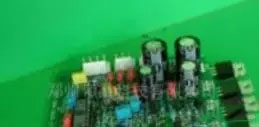
A circuit with a large power and capable of transmitting or radiating high-frequency electromagnetic waves to the outside through an antenna or a radio frequency transmitting head is called a radio frequency circuit. The characteristic of the RF circuit is that it can emit high-frequency electromagnetic waves to the outside world.
A high frequency circuit is a circuit that can operate a high frequency signal, receive a high frequency signal, or generate a high frequency signal, or amplify a high frequency signal, conduct a high frequency signal, or process a high frequency signal. The RF circuit is also a type of high frequency circuit.