
2019-07-10
In the field of microwave radio frequency, one of the biggest challenges when testing a device is how to eliminate harmful fixture effects. Port extension and TRL calibration are the easiest way to compensate for errors caused by inconsistent measurement planes and instrument measurement planes. One.
After calibration, the port extension feature can be used to compensate for errors in the extended measurement reference plane caused by the addition of cables, adapters, or clamps. When high measurement accuracy is required and there is no calibration piece of the same type as the device under test. TRL calibration is often required when measuring with a fixture or on a wafer using a probe. TRL calibration determines 12 error coefficients by measuring two transmission standards and one reflection standard, whereas conventional SOLT calibration measures one transmission. Standard (T) and three reflection criteria (SOL) to determine as many error coefficients
1. port extension implementation
Before the port is extended, two steps are generally required. The first step is to perform a full two-port calibration. This step removes the error of the vector network analyzer, the connection cable and various coaxial connectors, and connects all the fixtures. A good source match is made. The second step is to use the port extension for the test fixture. Cable or adapter calibration. This step can remove their insertion loss and response delay.
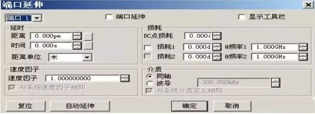
Port extensions include manual port extension and automatic port extension. Manual port extension is performed with certain characteristics of the known additional transmission line. Otherwise, automatic port extension can be used. The main interface of port extension is shown in Figure 1:
1.1 Manual port extension process
1) Select a calibrated S11 measurement (port 1); to extend port 2, select the calibrated S22 measurement.
2) Select the display format as phase format.
3) Connect OPEN or SHORT on the calibration reference plane to verify that the phase is near 0 or 0 within the frequency span.
4) Connect an additional transmission line or fixture and connect an OPEN or SHORT at the DUT position and then gradually increase the delay until the phase response is flat over the entire frequency span of interest.
5) If the loss of the additional transmission line is known, the loss compensation value can be directly input, and one (loss 1) or two data points (loss 1 and loss 2) can be used for loss compensation.
If the electrical length of the additional transmission line is known, it can be entered directly in the "time" of Figure 1. If the physical length of the additional transmission line is known, increase the "time" until the "distance"
Equal to the physical length of the additional transmission line. If you do not know the electrical length of the additional transmission line or the physical length of the additional transmission line, you must connect an opener or a shorter to the new reference plane. This allows automatic port extension to be used. .
1.2 Automatic Port Extension Process
1) After connecting an additional transmission line or fixture, connect an opener or a shunt to the new reference plane.
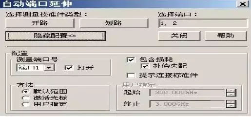
2) Click “Auto Port Extension” in Figure 1 and the dialog box shown in Figure 2 appears. Then click “Display Configuration” in Figure 2 to set it accordingly.
3) Click “Open” or “Short” in Figure 2 to calculate the automatic port extension. The automatically calculated delay and loss will be displayed in the corresponding text box in Figure 1. At the same time, the port will be opened automatically after the automatic calculation is completed. Extension function.
1.3 Implementation of automatic port extension
The interface for automatic port extension is shown in Figure 2.
2 TRL calibration
TRL (Thru-Reflect-Line) calibration includes a series of calibration techniques such as TRM (Thru-Reflect-Match). TRL calibration determines 12 error coefficients by measuring two transmission standards and one reflection standard, while traditional SOLT calibration The same error factor is determined by measuring one transmission standard (T) and three reflection standards (SOL).
If you need to perform TRL calibration on a vector network analyzer, since there are very few calibration parts that support TRL calibration, you must construct and define the same calibration piece for the device under test, and create 3 TRL standards than to manufacture 4 SOLT standards. Easier.
TRL calibration is suitable for narrowband calibration. Multiple transmission line standards must be used when broadband calibration is required. For example, the 2GHz to 26GHz band requires two transmission line standards, while in the low frequency band, the transmission line standard is particularly long.
The TRL calibration standard needs to define three standards: the straight-through standard, the reflection standard, and the transmission line standard. The following should introduce the matters that should be noted in the process of definition and construction of these three standards.
2.1 Direct standard
The straight-through standard can be zero length or non-zero length. Zero-length straight-through is more accurate because there is no loss and characteristic impedance. The electrical delay of the straight-through standard cannot be the same as the transmission line standard. If the phase and electrical length are precisely defined, Use it to establish a measurement reference plane during calibration.
2.2 Reflection standard
The reflection standard can be any physical device with a high reflection coefficient. The characteristics of the reflection standard connected to the two measurement ports must be identical. It is not necessary to know the amplitude of the standard reflection during calibration, but the phase must be known and its electrical length must be Within 1/4 wavelength. If the amplitude and phase of the reflection standard are precisely defined, it can be used to establish the measurement reference plane.
2.3 Transmission line standard
The transmission line standard is used to establish a calibrated measurement reference impedance. The TRL calibration has the following deficiencies due to the limitations of the transmission line standard:
· The transmission line standard must be the same as the straight-through standard impedance.
· The electrical length of the transmission line standard cannot be the same as the straight-through standard.
· The transmission line standard must have an appropriate electrical length over the entire frequency range. At each frequency point, the phase difference between the transmission line standard and the straight-through standard must be greater than 20 and less than 160. Therefore, the actual single transmission line can cover a frequency range of 8:1. In order to cover a wider frequency range, multiple transmission line standards are required.
· In the low frequency band, the transmission line standard will be particularly long. The optimal length of the transmission line standard is 1/4 wavelength of the geometrical frequency of the frequency span (starting frequency × the square root of the termination frequency).
2.4 Matching criteria
When the transmission line of the required length or loss cannot be manufactured, a matching standard can be used instead of the transmission line.
· The matching standard is a low-reflection terminal connected to the port.
· When calculating the error coefficient of TRL calibration, the matching standard is used as the transmission line with high loss and infinite length.
· The impedance of the matching standard becomes the reference impedance of the measurement.
3 TRL calibration implementation
To measure the S-parameters of a surface mount device using the TRL calibration function of the vector network analyzer, a corresponding test fixture must be fabricated. After the test fixture is fabricated, the TRL calibration standard can be fabricated on the corresponding test fixture. Below is the MAX2640 low noise. The S-parameter measurement and stability analysis of the amplifier (LNA) is an example to introduce the process of making TRL calibration standard parts.
Two sets of evaluation (EV) boards and one network analyzer (HP8753D) were used for the S-parameter measurement of the MAX2640. The first evaluation board (kit#1) IC was removed for calibration and the second evaluation board was used. (kit#2) for actual measurements, the evaluation board retains the IC, but no matching components.
1. Complete calibration of the dual port network, including the cable connected to the vector network analyzer.
2. When we measure the S-parameter of the IC without the matching component on the second evaluation board (kit#2), place the short wiring on the MAX2640 input and output pins on the first evaluation board (kit#1). Welding position (see Figure 3).
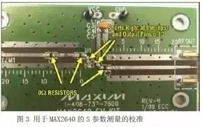
3. Adjust the network analyzer's port delay so that the input and output impedance at 315MHz are as close as possible to the short-circuit condition. At this point we can use the MAX2640 on the second evaluation board (kit#2). S-parameter measurements at the device pins.
4. Then modify the first evaluation board (kit#1) and shift the short wiring above to the placement point of the last matching component. Adjust the network analyzer's port delay again to make the input and output at 315MHz. The impedance is as close as possible to the short circuit condition.
5. Next, place the matching component back on the second evaluation board (kit#2) and measure the S-parameters of the IC with matching components on the evaluation board.
6. To verify the correctness of the S-parameters when testing only the IC (step 3 above), import the resulting S-parameters into ADS (microwave simulation software) and add matching components and transmission lines to the model. The parasitic effect is to add a 0.5pF capacitor to the input and output pins of the model. Then, the simulated performance curve of the established model and the IC S parameters measured with the matching components on the evaluation board (the above steps) 5) Compare.
4. test results
Figure 4 to Figure 9 are marked as follows:
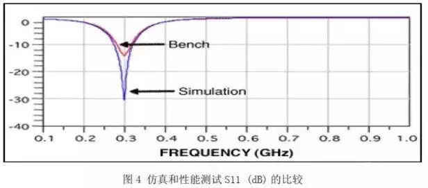
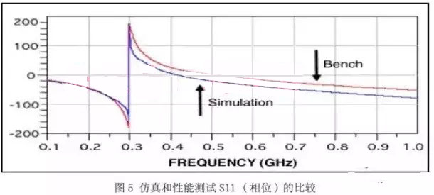
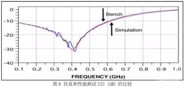
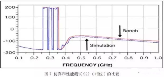
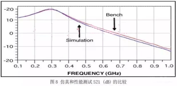
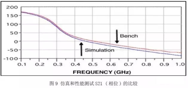
MAX2640_Epcos_1GHz_simulation: Only the ICs without matching components on the bench are measured, the measured S-parameters are used for simulation, and matching components are added to the ADS simulation model.
MAX2640_Epcos_1GHz_bench : S-parameter measurement of the IC after adding matching components to the evaluation board.
The above data indicates that the amplitude and phase performance are very close in the two tests performed. Excluding the small frequency offset, the simulation results (using the test S-parameters of the IC without matching components to model and add to the ADS model) After the component is matched, the simulation workbench is simulated. It is very close to the actual performance test (the actual performance is tested after adding the matching component on the evaluation board). So you can get the conclusion that the S parameter measured by the MAX2640 is Reliable for simulation and stability analysis.
5 Conclusion
This paper briefly introduces two methods for measuring surface-mount device (SMD) S parameters using vector network analyzers, namely port extension method and TRL calibration method. These two methods can be used according to the measurement accuracy requirements in the actual test process. The choice of height, when the required measurement accuracy is not high, generally choose the port extension method. When high measurement accuracy is required, and there is no calibration piece of the same type as the connector of the device under test, the TRL calibration method is often selected.