- HOME
- IC PARTNER
- IC Design
- AVR RF/ Atmel

We are pleased to introduce you to our crystal unit
Items to Confirm (designing of oscillation circuit)
· Selection Guidance for crystal unit
· Crystal Products Lineup
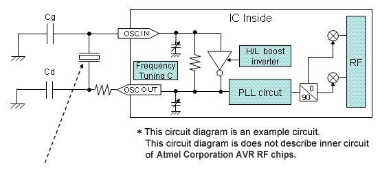
· Oscillation Circuit and Selection Guidance of Crystal Unit.
· Precautions for designing of PCB Board
Crystal Recommendations for Atmel Corporation "AVR RF chips".
· Recommendations AVR RF chips.
In realizing low power consumption RF designs, the following factors should be taken into consideration.
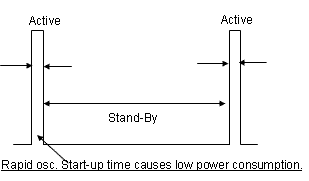
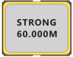
1. Oscillation start-up time
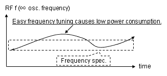
2. Frequency tuning
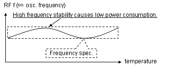
3. Lower BER(Bit Error Rate) over operating temperature
|
No. |
Oscillation Circuit Factor |
2.4 GHz |
|
< AT crystal unit spec.> |
||
|
1 |
Quick oscillation start-up time |
*Lower ESR(R1) |
|
2 |
Easy frequency control |
*proper frequency sensitivity |
|
3 |
Lower BER |
*High frequency stability |
|
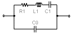
MHz Crystal equivalent circuit |
|
|
Rapid Oscillation start-up time |
|
|
Suitable Frequency Tuning |
|
|
Suitable Frequency Tuning |
|
|
Higher Frequency Stability |
|
|
QMEMS Technology |
|
|
Worldwide |
ATmega256RFR2 |
AT86RF233 |
AT86RF212B |
|||
|
US |
Europe |
Japan |
Asia |
|||
|
ZigBee |
2400 to 2483.5 MHz |
700/800/900 MHz |
||||
|
Recommendable |
S2520-16.000M-9-20-20-A |
|||||
Notes: Above recommendations are based on actual evaluation results and intended to support users in picking the right components. As the actual board layout and choice of external components influences the best suitable crystal load capacitance, We does not assume any responsibility and grant warranty for above recommendations. Users design must be verified and decided by own and individual evaluation.
Please refer to Atmel Corporation AVR RF chips manual for designing.
*ZigBee is a registered trademark of Koninklijke Philips Electronics N.V.
Please note: to design oscillation circuit, you need to confirm the electronic characteristics as follows:
Oscillation allowance and Negative resistance (-R):
You need to confirm oscillation capability.
We recommend the condition: (-R) / ESR > 5
* -R: Negative resistance, ESR: Equivalent Series Resistance
Drive Level:
You need to confirm if oscillation is stable, and if the drive level is within the specification.
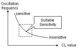
Load Capacitance:
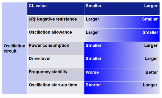
Load capacitance affects frequency stability, oscillation allowance, negative resistance, and start-up time of oscillation.
In addition the load capacitance is determinative factor of crystal unit's load capacitance (CL value) directly.
* frequency stability: frequency deviation out of circuit conditions.
When Customer selects crystal unit, lload capacitance (CL value) is an important factor of the selection.
For instance, crystal with small CL(7.0 pF) makes larger oscillation allowance, smaller current consumption and worse frequency stability, like below table.
Oppositely, crystal with large CL(12.5 pF) makes smaller oscillation allowance, larger current consumption and better frequency stability.
Please select it in consideration of these characteristics.
|
Product |
Size [mm] |
Applications |
Images |
|
S2520 |
2.5×2.0×0.55t |
-Mobile phone,Bluetooth,W-LAN |
|
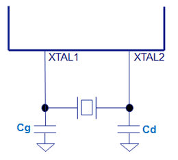
Pin number of XTAL1/XTAL2
|
|
XTAL1 |
XTAL2 |
|
ATmega256RFR2 |
57 |
56 |
|
ATmega128RFA1 |
57 |
56 |
|
AT86RF23x, 212/212B |
26 |
25 |
Internal trimming capacitors of AVR RF chips (Default)
|
Ctrim (XTAL_TRIM) |
0 |
pF |
|
IC |
product |
Freq.[Hz] |
CL*1 |
f_tol*2 |
Product |
External parts *4 |
Package |
|
|
Cg |
Cd |
|||||||
|
ATmega256RFR2 |
S2520 |
16M |
9.0 |
10 |
S2520-16.000M-9-10-10-A |
12 |
12 |
2.5x2.0x0.55 |
|
ATmega128RFA1 |
||||||||
|
AT86RF233 |
20 |
S2520-16.000M-9-20-20-A |
12 |
12 |
||||
|
AT86RF231 |
||||||||
|
AT86RF212B |
||||||||
|
AT86RF212 |
||||||||
Notes:*
1. Load capacitance.
2. Frequency tolerance (standard)
3. Two digits of the product code is packing specification, please refer here for the detail.
4. Above recommendations are based on actual evaluation results and intended to support users in picking the right components. And the results are only according to the sample set that received from our customers, so it is not including the dispersion trend of IC and the external parts.
As the actual board layout and choice of external components influences the best suitable crystal load capacitance, We do not assume any responsibility and grant warranty for above recommendations. Users design must be verified and decided by own and individual evaluation.